Origin of degenerate bound states in the continuum in a grating waveguide Parity symmetry breaking due to mode crossing C.B. Reynolds Vl.V. Kocharovsky V.V. Kocharovsky
2025-04-29
0
0
7.67MB
25 页
10玖币
侵权投诉

Origin of degenerate bound states in the continuum in a grating waveguide:
Parity symmetry breaking due to mode crossing
C.B. Reynolds, Vl.V. Kocharovsky, V.V. Kocharovsky
Department of Physics and Astronomy, Texas A&M University, College Station, TX 77843, USA
(Dated: August 15, 2023)
We explain the origin of bound states in the continuum (BICs) in a planar grating waveguide, in
particular, a mechanism for formation of degenerate BICs, via the analytical theory of the infinite-
grating eigenmodes. Conventional symmetry-protected BICs are formed at normal incidence mainly
by a single infinite-grating eigenmode that has an odd spatial parity on both sides of the BIC
resonance. The odd parity is the reason for a cutoff from the radiation-loss channel and appearance of
such BICs. The mechanism of emergence of a degenerate BIC in a vicinity of a degenerate frequency
of two infinite-grating eigenmodes is different. The degenerate BIC is formed by an anti-phased
coherent superposition of two crossing infinite-grating eigenmodes both of which possess a mixed
parity and experience parity symmetry breaking as the frequency scans through the degeneracy
point. In this case a cutoff from the radiation-loss channel and extremely high-Q narrow resonance
is achieved due to the destructive interference of the two crossing eigenmodes. Implementation of
such a mechanism can be instructive for designing BICs in other photonic crystals and structures.
I. INTRODUCTION: A BOUND STATE IN THE
CONTINUUM AS A RESOURCE FOR A
SOLITARY HIGH-Q RESONANCE
By means of the analytical theory of the infinite-
grating eigenmodes [1], we disclose a distinct, explicit
mechanism leading to the formation of the degenerate
bound states in the continuum (BICs) and an entire hier-
archy of BICs in a planar grating waveguide (1D grating
slab with in-plane C2symmetry, Fig. 1).
Namely, far from the crossing points of the infinite-
grating-eigenmode dispersion curves shown in Fig. 2, one
has only symmetry-protected BICs formed at normal in-
cidence mainly by just one relevant single infinite-grating
eigenmode whose in-plane spatial profile is purely odd
with respect to the in-plane mirror symmetry. Such a
BIC waveguide eigenmode involves an admixture of other
odd-parity infinite-grating eigenmodes due to reflection
at the boundaries with the substrate and cover, but is
completely disconnected from the zeroth spatial Fourier
harmonic designed to be the only radiation-loss channel
available in the grating waveguide.
On the contrary, a degenerate BIC arises in a vicin-
ity of a degeneracy point where dispersion curves of two
infinite-grating eigenmodes of opposite parity intersect,
as at D0
2,3in Fig. 2. This couple forms an anti-phased
superposition and constitutes a degenerate-BIC eigen-
mode of the grating waveguide due to modes’ mutual
reflections at the borders of the grating layer. Although
both infinite-grating eigenmodes possess a mixed parity
and undergo a parity symmetry breaking in a vicinity of
the degeneracy point, their anti-phased superposition re-
mains decoupled from the only radiation channel – emis-
sion of the zeroth spatial Fourier harmonic outside the
grating waveguide into the cover and substrate. All other
Fourier harmonics of higher Bragg diffraction orders can-
not be emitted into the cover and substrate because they
are evanescent there. Such a phenomenon of destruc-
tive interference producing the degenerate-BIC waveg-
FIG. 1. The planar grating waveguide. (a) Geometry: the
grating of thickness Land period λgsandwiched between the
substrate and cover with permittivities ε−and ε+, respec-
tively. (b) The wave vectors associated with the propagating
or evanescent eigenmodes inside the grating and the plane
waves (Fourier harmonics) of different Bragg diffraction or-
ders in the substrate and cover, p= 0,±1, . . ..
uide eigenmode decoupled from the radiation-loss chan-
nel is of general nature and could exist in a number of
other photonic structures and crystals.
The BIC waveguide eigenmode demonstrates an ex-
tremely narrow, solitary high-Q resonance despite the
fact that a continuum of plane waves in a wide range of
frequencies and wave vectors around the resonant ones
arXiv:2210.00628v2 [physics.optics] 13 Aug 2023

2
FIG. 2. Hierarchy of dispersion curves k2
zn (ω), Eq. (24), and
their intersections (degeneracy points) for the infinite-grating
eigenmodes in the titanium-oxide grating; ε1= 6.25, ε2=
3.9, ρ = 0.39183; kx= 0. The symbol Dl
n,n+1 labels the l-th
intersection of the n-th and (n+1)-th eigenmodes and signifies
the associated BIC.
can freely escape from the waveguide into the cover and
substrate. The latter distinguishes the phenomenon of
BICs from a conventional trapping of fields inside waveg-
uides or cavities which is based on a complete prevention
(say, by means of reflection) of the entire continuum of
waves from propagating outside the waveguide or cav-
ity. The search, analysis, design, and applications of the
BICs constitute a very active field of modern research in
a variety of wave systems, especially in photonics, despite
the BIC having first been suggested for matter waves in
quantum mechanics [2–4]. The mechanisms of forma-
tion and properties of various BICs in photonic struc-
tures had been widely discussed in the literature (see, for
example, reviews [5–9] and papers [10–21]). In particu-
lar, the BIC in the grating layer sandwiched by the cover
and substrate had been demonstrated via numerical sim-
ulations for a particular set of parameters in [10]. Yet,
despite the fact that the planar lamellar (that is, uniform
along yaxis) grating waveguide is one of the most basic,
simple examples of photonic structures supporting BICs,
a full analytical theory of BICs, in particular, degener-
ate BICs, in the grating waveguide and eigenmode-based
understanding of degenerate-BIC appearance have been
missing until now. This approach, in particular, reveals
exact analytical formulas clarifying universal features of
the BIC formation which, otherwise, would stay hidden.
Apparently, the main reason for that is the fact that
most works on BICs are based on ad hoc numerical sim-
ulations dominating modern analysis of photonic-crystal
structures. They employ various software based on finite-
element modeling like COMSOL [22], rigorous coupled
wave analysis (RCWA) [24], finite-difference time-domain
(FDTD) method [23], codes for layered periodic struc-
tures [25], finite element method (FEM) [15], etc.
Another reason is that the BIC-formation mechanism
in such a simple, basic photonic structure as the pla-
nar lamellar-grating waveguide turns out to be so special
that it simultaneously merges almost all other known
mechanisms leading to the BIC formation (see reviews
[5–9]), including mechanisms of the symmetry-protected
BIC, accidental BIC, single-resonance parametric BIC,
coupled multiple resonances (Friedrich–Wintgen, but not
Fabry–P´erot) BIC, interference-based BIC through pa-
rameter tuning, and topologically-protected BIC. A more
detailed discussion of this fact requires results presented
in sections II–VI and is postponed to sect. VII.
The present paper is devoted to introducing such an
analytical eigenmode approach per se, not to its thor-
ough application for classification of all possible BICs or
discovery of new BICs. We give a new interpretation of
the known symmetry-protected BIC, in particular, de-
generate BICs, but do not attempt, within the scope of
the present paper, to design a BIC of a new type. It
is remarkable how merely splitting the central dielectric
layer of the planar waveguide into two alternating sec-
tions of lengths d1, d2(with a fill factor ρ=d1/(d1+d2))
and different permittivities ε1, ε2converts an elementary,
trivially soluble problem of the planar dielectric waveg-
uide [26–28] into a rich, complex problem demonstrating
many generic features of optical crystals.
Optical gratings and related waveguides are also in-
teresting by themselves, irrespective to BICs, since they
have found numerous applications and been studied for
decades (see, for instance, [26,27,29–37] and references
therein). One of the most elegant methods of their stud-
ies is based on the analysis of eigenmodes that is very
fruitful both for the analytical theory and numerical sim-
ulations (see [1,28–31] and references therein). An-
other, more straightforward method is the Fourier modal
method which prevails in the literature and is known as
the rigorous coupled wave theory in the diffractive optics
community [11,29,30] or the scattering-matrix approach
in the photonic-crystal community [32–37].
In the present paper, we consider a particular example
of a waveguide eigenmode – a degenerate BIC originating
due to the mechanism outlined in the second paragraph
of the paper. The in-plane x-wavenumber of that BIC
waveguide eigenmode is chosen to be near the Γ-point –
the center of the first Brillouin zone of the grating, that
is kx≈0. (We assume that ky= 0 since we consider
only the standard, invariant in the ydirection, grating
problem when fields are uniform along the yaxis and
propagate in the xz-plane. So, we leave the conical case
of diffraction [38] aside.) This choice is predetermined by
strongly enhanced backscattering coupling in this excep-
tional high-symmetry point in the momentum space so

3
that the corresponding eigenmode looks more like a cav-
ity eigenmode rather than a waveguide eigenmode. In
fact, it has been shown by means of the representation
theory that in the standard photonic crystal slabs the
symmetry-protected BICs exist only at the center of the
Brillouin zone [20,21]. At wavenumbers away from the
Gamma point kx= 0, the waveguide eigenmode radi-
ates and forms a leaky resonance. The latter had been
illustrated in [10] by a numerical example.
We assume that just the central, zeroth diffraction or-
der p= 0, spatial Fourier harmonic is emitted out of the
planar grating layer into the cover and substrate, while
all higher-order, p̸= 0, Fourier harmonics are evanescent
and, hence, do not contribute to the radiation losses. Ac-
cording to the plane-wave dispersion relation, the p-th
Fourier harmonic becomes evanescent in the cover (su-
perscript “+”) or substrate (superscript “-”) when its
z-wavenumber squared turns negative:
(k±
zp)2=ε±ω2/c2−(kx+pkg)2<0.(1)
Here ε+or ε−is the permittivity of the cover or sub-
strate, respectively. For modes at the center of the first
Brillouin zone, kx= 0, the p-th Fourier harmonic ceases
to provide a radiation-loss channel when
ε±<2πcp
ωλg2.(2)
Below we mainly focus on the degenerate BIC originat-
ing from the degeneracy point D0
2,3(see Fig. 2) when the
condition (2) is satisfied for all nonzero diffraction orders
p=±1,±2, . . .. The analysis of the degenerate BICs at
other mode-crossing points Dl
n,n+1 is alike.
The content of the paper is as follows. We overview the
genesis and field constituents of BICs in a planar grating
waveguide in sect. II. In sect. III we present the nec-
essary analytical formulas describing the infinite-grating
eigenmodes as well as the waveguide eigenmodes. In sect.
IV we disclose the universality of the behavior of the
infinite-grating eigenmodes within the vicinity of a mode
crossing point and a remarkable connection between the
dispersion degeneracy and parity symmetry breaking of
the eigenmode spatial profiles changing from odd to even,
or vise versa. We elaborate both on the special case of
normal incidence, kx= 0, and the case of a nonzero in-
plane wavenumber, kx̸= 0. In sect. V we explain how
to design a waveguide manifesting a degenerate BIC at
a given frequency. It is done on the basis of a numerical
example related to a waveguide based on titanium oxide
(TiO2) – an optical material known for many applications
in photonics. The mechanism behind the emergence of
the degenerate BIC is explained and detailed in sect. VI.
It involves a parity symmetry breaking, that occurs in ac-
cord with the above universality, and a decoupling from
a radiation-loss channel due to destructive interference
at mode crossing. Conclusions, discussion of the simul-
taneous manifestation of other known BIC mechanisms
in the formation of the above BIC, and other comments
make up sect. VII.
II. GENESIS AND FIELD CONSTITUENTS OF
BICS IN A PLANAR GRATING WAVEGUIDE
We employ the eigenmode approach which, in the case
of BICs in the planar grating waveguide shown in Fig. 1,
is based on the hierarchy of the following three field con-
stituents: (i) the plane waves, (ii) the infinite-grating
eigenmodes, and (iii) the waveguide eigenmodes.
The plane waves are the simplest field configurations
possessing a quasi-harmonic temporal-spatial profile ∝
eikzp z+i(kx+pkg)x−iωt satisfying a standard dispersion law,
k2
zp + (kx+pkg)2=εω2/c2,(3)
in a uniform medium. The latter means that their
phase speed depends on a permittivity εof the dielec-
tric medium in which they propagate. The prefix ’quasi’
indicates that the frequency ωand the z-wavenumber
kzp, in general, are complex-valued.
A single plane wave with a wave vector k= (kx, kz)
together with its mirror counterpart with a wave vector
k′= (kx,−kz) constitutes a waveguide eigenmode only
in the trivial case of a slab waveguide with a homoge-
neous central dielectric layer of permittivity ε. A homo-
geneous slab waveguide can be viewed as the zeroth-order
approximation for the grating waveguide if we choose its
core permittivity equal to the average permittivity of two
grating sections, ε= (ε1d1+ε2d2)/λg;λg=d1+d2.
FIG. 3. The first three transverse guided TE-eigenmodes of
a homogeneous slab waveguide of thickness L= 0.71587λg:
Dispersion curves kxn(ω) (left) and spatial z-profiles E(n)
y(z)
(right). The permittivities of the central layer, substrate and
cover are ε= 4.8208, ε−= 2 and ε+= 1, respectively.
It is immediate to find all guided TE-modes of such a
slab waveguide (see, e.g., [26]). The dispersion curves and
spatial z-profiles of the first three transverse eigenmodes

4
guided by a slab waveguide are illustrated in Fig. 3. We
enumerate them by the integer nequal to the number of
extrema in the z-profile of the electric field E(n)
y(z). All
extrema are localized within the central dielectric layer,
z∈(0, L). The eigenmode amplitude is constant along
the xaxis. For a given frequency ω, the field profiles
{E(n)
y(z)|n= 1,2, . . .}constitute a series of monochro-
matic transverse eigenmodes associated with a discrete
set of solutions for the eigen x-wavenumber, {kxn(ω)},
to the following dispersion equation
ωL(ε−ε−)
c= (n−1)π+ tan−1rb
1−b+ tan−1rb+a
1−b;
a=ε−−ε+
ε−ε−, b =(ckx/ω)2−ε−
ε−ε−, n = 1,2,3, . . . .
(4)
The series starts from the fundamental eigenmode n= 1.
All those guided modes in the slab have an angle of in-
cident lying inside a sector of the total internal reflection.
Hence, they are evanescent, that is, do not radiate out-
side the slab and ideally have an infinite Q factor. How-
ever, they are not BICs since, for a given incident angle,
they have discrete frequencies lying completely outside
the continuous spectrum of the leaky, radiation waves.
The infinite-grating eigenmodes [1] are also closely re-
lated to the plane waves in a uniform dielectric medium.
Yet, they are strongly restructured by multiple Bragg
reflections on the 1D lattice of the alternating permittiv-
ities of the grating sections. Such an umklapp scattering
can be visualized via a superposition of the parabolic
uniform-medium dispersion curves k2
zp(kx) of various
diffraction orders p= 0,±1,±2, . . . given by Eq. (3) as is
shown in Fig. 4. An effective uniform medium with the
average grating permittivity ε= (ε1d1+ε2d2)/(d1+d2)
yields a good zeroth-order approximation for the disper-
sion curves of the infinite-grating eigenmodes (cf. Fig. 2).
The main nontrivial feature here is opening the gaps in
the k2
zn spectrum near avoiding-crossing points. These
gaps are induced by the Bragg-reflection resonances. The
frequency for the plot in Fig. 4is chosen to be the degen-
erate frequency for the second and third infinite-grating
eigenmodes, ω=ωc≡4c
λg. In this case the gap at the
intersection of the dispersion curves k2
z2and k2
z3is absent.
Contrary to the guided modes of the homogeneous
slab, the infinite-grating eigenmodes are the field con-
figurations possessing a trivial quasi-harmonic temporal
and spatial z-profile ∝eikzn z−iωt, but a nontrivial spa-
tial x-profile fn(x) (see Fig. 5and Eq. (6)) such that it
remains invariant in the course of propagation inside the
infinite grating despite a persistent in-plane Bragg scat-
tering. Such an invariance occurs only for a discrete set
of eigen z-wavenumbers kzn enumerated by the integer
n= 1,2, . . . (see Fig. 2). Thus, the infinite-grating eigen-
modes take care of the field boundary conditions and field
transformation at all yz-plane boundaries between alter-
nating, along the xaxis, sections of the grating, but do
not take into account the grating-waveguide boundaries
FIG. 4. ”Energy bands and gaps” of the 1D grating: An ex-
tended Brillouin zone representation for the dispersion curves
of the infinite-grating eigenmodes, (c/ω)2k2
zn (kx), Eq. (24),
(thick black curves) approximated by a superposition of the
parabolic uniform-medium dispersion curves, (c/ω)2k2
zp (kx),
Eq. (3), (dashed color curves) shifted due to the Bragg reflec-
tion resonances of various orders by multiples of the grating
wavenumber pkg= 2πp/λg, p = 0,±1,±2, . . .. The permit-
tivity of the effective uniform medium, ε= (ε1d1+ε2d2)/(d1+
d2)=4.8208, is equal to the weighted sum of the permittivi-
ties ε1= 6.25, ε2= 3.9 of the two grating sections of lengths
d1= 0.39183λg, d2= 0.60817λg, respectively; ω= 4c/λg.
with the substrate and cover. For zero in-plane wavenum-
ber kx= 0, as is illustrated in Fig. 5, the spatial parity of
the x-profiles f1, f3, f5, . . . is purely even while the spa-
tial parity of the x-profiles f2, f4, . . . is purely odd. Each
infinite-grating eigenmode lives inside the infinite grat-
ing independently of others, is a superposition of many
spatial Fourier harmonics (partial plane waves), and rep-
resents a photon dressed via Bragg, umklapp scattering.
At last, the waveguide eigenmodes are the field configu-
rations which follow a quasi-harmonic evolution ∝e−iωmt
with a complex-valued eigenfrequency ωm=ω′
m−iω′′
m,
enumerated by a composite integer m, while possessing
a stationary (invariant in time) spatial structure. Any,
say the m-th, waveguide eigenmode inside the grating
layer is a superposition of many infinite-grating eigen-
modes, coupled to each other via mutual reflections at
the grating-layer borders with the cover and substrate.
Thus, the discrete set of waveguide eigenmodes is de-
termined by and take care of both sets of boundary
planes and corresponding boundary conditions of con-
tinuity of the tangential components of the electric and
magnetic fields: Two xy-planes, at z= 0 and z=L

5
FIG. 5. Longitudinal (in-plane) x-profiles for the first five
eigenmodes of the infinite grating with two sections of lengths
d1= 0.39183λg, d2= 0.60817λgand permittivities ε1=
6.25, ε2= 3.9, respectively; kx= 0, ω =5c
λg. For simplicity’s
sake, the plotted functions fn(x) differ from those in Eq. (6)
by a phase factor eiφnmaking them real-valued. Note a slight
discontinuity of the derivatives dfn/dx at the boundaries be-
tween the grating sections.
along the zaxis, which determine the series of trans-
verse eigenmodes in the homogeneous slab waveguide as
well as the infinite sequence of yz-planes, at x=pλg
and x=d1+pλg, p = 0,±1,±2, . . ., along the xaxis,
which determine the series of the infinite-grating eigen-
modes. Contrary to the slab’s transverse modes and
infinite-grating eigenmodes, the grating waveguide eigen-
modes possess two-dimensional spatial structure which is
nontrivial in both transverse, z, and longitudinal, x, di-
rections as is shown in Fig. 6.
The waveguide eigenmodes, accordingly, can be enu-
merated by a composite integer m= (mz, mx). Its first
component, mz, indicates the number of field extrema
in the transverse direction zand can be traced to the
FIG. 6. Two-dimensional (in the xz-plane) field patterns,
Re(E(m)
y), of first lower frequency grating-waveguide eigen-
modes at a small x-wavenumber, kx≈0. The composite
index (mz, mx) in each row labels the number of transverse
(mz) and longitudinal (mx) field extrema per the grating pe-
riod λg. The eigenmodes in each row pair differ by the value
of the binary index, s= 0 or s= 1, labeling modes with the
odd or even parity of the field’s x-profile, that is, with the
high or low Q factor. The lengths and permittivities of the
two grating sections are d1= 0.39183λg, d2= 0.60817λgand
ε1= 6.25, ε2= 3.9, respectively. The thickness of the grating
layer is L= 0.71587λg. The permittivities of the substrate
and cover are ε−= 2 and ε+= 1, respectively. Positive and
negative field values are marked in red and blue, respectively.
order nof the corresponding transverse mode of the ho-
mogeneous slab in Eq. (4), mz=n. The second compo-
nent, mx, indicates the number of field extrema in the
longitudinal direction xper the grating period λgand
depends on the Brillouin zone index, p, of the relevant
infinite-grating eigenmodes. Along with the composite

摘要:
展开>>
收起<<
Originofdegenerateboundstatesinthecontinuuminagratingwaveguide:ParitysymmetrybreakingduetomodecrossingC.B.Reynolds,Vl.V.Kocharovsky,V.V.KocharovskyDepartmentofPhysicsandAstronomy,TexasA&MUniversity,CollegeStation,TX77843,USA(Dated:August15,2023)Weexplaintheoriginofboundstatesinthecontinuum(BICs)inap...
声明:本站为文档C2C交易模式,即用户上传的文档直接被用户下载,本站只是中间服务平台,本站所有文档下载所得的收益归上传人(含作者)所有。玖贝云文库仅提供信息存储空间,仅对用户上传内容的表现方式做保护处理,对上载内容本身不做任何修改或编辑。若文档所含内容侵犯了您的版权或隐私,请立即通知玖贝云文库,我们立即给予删除!
相关推荐
-
曲一线系列初中《5中考3年模拟》2023专题解释全国道德与法治资料包05专题五 走进社会生活 遵守社会规则VIP免费

 2024-11-21 24
 -
曲一线系列初中《5中考3年模拟》2023专题解释全国道德与法治资料包05专题五 走进社会生活 遵守社会规则VIP免费
 2024-11-21 24
 -
曲一线系列初中《5中考3年模拟》2023专题解释全国道德与法治资料包03专题三 青春时光 做情绪情感的主人VIP免费
 2024-11-21 16
 -
曲一线系列初中《5中考3年模拟》2023专题解释全国道德与法治资料包03专题三 青春时光 做情绪情感的主人VIP免费
 2024-11-21 22
 -
曲一线系列初中《5中考3年模拟》2023专题解释全国道德与法治资料包02专题二 友谊的天空 师长情谊VIP免费
 2024-11-21 19
 -
曲一线系列初中《5中考3年模拟》2023专题解释全国道德与法治资料包02专题二 友谊的天空 师长情谊VIP免费
 2024-11-21 20
 -
曲一线系列初中《5中考3年模拟》2023专题解释全国道德与法治资料包01专题一 成长的节拍 生命的思考VIP免费
 2024-11-21 25
 -
曲一线系列初中《5中考3年模拟》2023专题解释全国道德与法治资料包01专题一 成长的节拍 生命的思考VIP免费
 2024-11-21 24
 -
曲一线系列初中《5中考3年模拟》2023专题解释全国道德与法治资料包《53中考》全国道德与法治资料包VIP免费
 2024-11-21 27
 -
曲一线系列初中《5中考3年模拟》2023专题解释全国道德与法治资料包07专题七 坚持宪法至上 崇尚法治精神VIP免费
 2024-11-21 19
分类:图书资源
价格:10玖币
属性:25 页
大小:7.67MB
格式:PDF
时间:2025-04-29
作者详情
相关内容
-
2025届重庆市西南大学附属中学高三下学期5月全镇模拟物理试题(含答案)
分类:中学教育
时间:2025-12-31
标签:无
格式:PDF
价格:10 玖币
-
2025届重庆市西南大学附属中学高三下学期5月全镇模拟化学试题(含答案)
分类:中学教育
时间:2025-12-31
标签:无
格式:PDF
价格:10 玖币
-
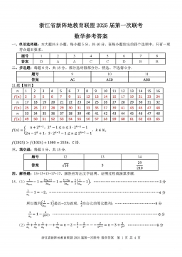
2025届浙江省新阵地联盟高三10月联考数学答案
分类:中学教育
时间:2025-12-31
标签:无
格式:PDF
价格:10 玖币
-
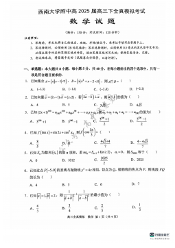
2025届重庆市西南大学附属中学高三下学期5月全镇模拟数学试题(含答案)
分类:中学教育
时间:2025-12-31
标签:无
格式:PDF
价格:10 玖币
-

2025届重庆康德三诊英语+答案
分类:中学教育
时间:2026-01-03
标签:无
格式:PDF
价格:10 玖币