On the development of a new coplanar transmission line based on gap waveguide
2025-05-02
0
0
1.55MB
17 页
10玖币
侵权投诉
1
C. BIURRUN-QUEL et al.: ON THE DEVELOPMENT OF A NEW COPLANAR TRANSMISISON LINE BASED ON GAP WAVEGUIDE.
*
Carlos Biurrun-Quel, Student Member, IEEE, Jorge Teniente and Carlos del-Río, Senior Member, IEEE
Abstract— A combination of gap waveguide technology and the
traditional coplanar waveguide is studied in detail and
demonstrated experimentally for the first time. This novel
metamaterial transmission line is presented in three different
configurations and offers a broadband operation, low loss, and low
dispersion characteristics. Analytical expressions for its
characteristic impedance and effective permittivity are provided
and validated by Finite Element Method simulations. The loss and
dispersion of the line are analyzed with an Eigenmode solver. The
proposed line prevents the propagation of substrate modes in the
band of operation at the same time it reduces the dielectric loss in
the line due to a higher concentration of the E-field over the air.
Moreover, its coplanar layout facilitates the integration of active
components. As such, it is considered to constitute a potential key
element in the development of more efficient, millimeter wave
systems.
Index Terms—CPW, electromagnetic band gap, gap waveguide,
metamaterial, millimeter wave and terahertz components and
technologies, on-wafer measurements, periodic structures, planar
transmission lines, sub-millimeter, transmission line theory.
I. I. INTRODUCTION
ICROWAVE engineers have been constantly
pursuing the development of new alternatives for
propagating the electromagnetic fields in the most
advantageous manner for diverse, specific target scenarios. This
everlasting goal is fostered by a continuous demand for
progress due to the emergence of new applications and services,
which may present more stringent requirements that might not
be satisfied by the current technologies. In addition, the
microwave and mmWave parts of the spectrum are increasingly
being filled, which encourages the pursuit for expansion
towards higher, less populated frequency bands. As a result of
this development, a plethora of available technologies have
been proposed during the last century, with the advent of planar
transmission lines [1], [2] and hollow, metallic waveguides, but
specially over the last two decades, with the development of
Substrate Integrated Waveguides [3] and Gap Waveguide
technology with all its different configurations [4][7].
Depending on the targeted application and frequency band,
one may find different challenging aspects when designing a
*
This work was funded by the FPU Program (FPU18/00013) and PID2019-
109984RB-C43 FRONT-MiliRAD, from the Spanish Ministry of Science and
Innovation (Corresponding author: C. Biurrun-Quel).
C. Biurrun-Quel is with the Antenna Group, Department of Electrical,
Electronic and Communications, and the Institute of Smart Cities, Public
University of Navarra, Pamplona, 31006 Spain. (e-mail:
carlos.biurrun@unavarra.es).
microwave/mmWave circuit in planar technology. For instance,
whereas hollow metallic waveguides present the lowest
attenuations for mmWave frequencies, a planar technology
(typically, coplanar waveguides, CPW) is required for
integrating active devices such as oscillators, (photo)diodes or
transistors. One challenging issue concerning these planar
technologies involve the propagation of substrate modes,
especially when the substrate presents a back metallization
(typically required for mechanical support). These modes incur
in additional loss and become more important when increasing
the frequency of operation. This is mainly because the number
of propagated substrates modes increases with the electrical
thickness of the substrate [8], which imposes a limitation, since
the thickness of commercially available substrates is
constrained by mechanical aspects (found either during their
fabrication or just due to an unfeasible handling).
One way to prevent substrate modes is the inclusion of
metallic vias along the perimeter of the line. This solution,
however, is not applicable to every material. For instance, some
polymers are difficult to drill without compromising the
mechanical stability (drilling holes make the surrounding parts
of the substrate brittle). Other substrates broadly employed in
microelectronics (such as Silicon Si or Indium Phosphide
InP) require complex chemical processes to etch these holes,
increasing the overall costs. Furthermore, the higher the
frequency of operation, the lower the required via separation
and size, which challenges the state-of-the-art CNC machining
techniques. On top of that, these via holes require inner-wall
metallization, a step that might not be feasible for very small
via dimensions, or that may just increase the costs substantially.
In an attempt to overcome these limitations, we presented in
2021 the conceptualization of a new planar transmission line
that combined CPWs with the basic theory of Gap Waveguides
[9]. This line, depicted in Fig. 1 (i), consists of a coplanar
waveguide on a dielectric substrate supported on top of an
artificial magnetic conductor (AMC), which prevents the
propagation of the EM fields inside the substrate below the
conductors. This conceptualization resulted from a natural
correspondence between the traditional transmission lines and
J. Teniente is with the Antenna Group, Department of Electrical, Electronic
and Communications, and the Institute of Smart Cities, Public University of
Navarra, Pamplona, 31006 Spain. (e-mail: jorge.teniente@unavarra.es).
C. del-Río is with the Antenna Group, Department of Electrical, Electronic
and Communications, and the Institute of Smart Cities, Public University of
Navarra, Pamplona, 31006 Spain. (e-mail: carlos@unavarra.es).
Color versions of one or more of the figures in this article are available
online at http://ieeexplore.ieee.org
M

2
C. BIURRUN-QUEL et al.: ON THE DEVELOPMENT OF A NEW COPLANAR TRANSMISISON LINE BASED ON GAP WAVEGUIDE.
their gap waveguide counterparts, shown in Fig. 1. The main
C
(GapCPW) is that propagation inside the substrate underneath
the coplanar grounds is prevented due to the virtual stopband
created by the PEC/PMC parallel plates. That previous work
also addressed an additional modification to the proposed line,
which consisted of including a metallic encapsulation on top of
the line (Fig. 1 (j)). However, this encapsulation may excite
cavity/parallel-plate modes between the top metallic
encapsulation and the coplanar grounds. For this reason, an
enclosed encapsulation was also proposed and coined as
, Fig. 1 (k), in
clear resemblance to the inverted microstrip gap waveguide [5],
[7], [10]. This encapsulation serves three main purposes. First,
it connects both lateral grounds, preventing the propagation of
the typically undesired slotline odd mode. Secondly, it allows
the EM fields to couple to this metallic encapsulation and to
propagate over the air. Thirdly, it provides an
electromagnetically compatible encapsulation to isolate and
package the circuits, while preventing cavity modes.
The present work aims to shed light onto these new
transmission lines by providing some design rules and
expressions for calculating their impedance, as well as useful
insight into their simulation with commercial software
packages. Moreover, experimental validation of these new
types of transmission lines is also provided for the first time.
The remainder of this manuscript is structured as follows:
Section II reviews the theory and principle of operation behind
the concept of Gap Coplanar Waveguides. Accurate
expressions for the effective permittivity and characteristic
impedance are then provided in Section III, obtained by means
of Conformal Mapping. The values computed with these
expressions will be then compared to the impedance calculated
by Finite Element Method (FEM). Section IV continues
providing useful insight into the design and simulation of these
lines, addressing their simulation with an Eigenmode solver.
Fig. 1. Summary of the typical transmission lines and waveguide-(k) are the ones proposed. E-field lines of the
dominant mode are also plotted for each case. Blank spaces are considered air/vacuum.

3
C. BIURRUN-QUEL et al.: ON THE DEVELOPMENT OF A NEW COPLANAR TRANSMISISON LINE BASED ON GAP WAVEGUIDE.
The analysis is continued in Section V, where a comprehensive
study of the loss in the lines is presented. It must be noted that,
throughout this work, the commercial software ANSYS
Electromagnetics Desktop (traditionally known as HFSS) [11]
has been employed. Nevertheless, any other simulator packages
should be suitable for designing and simulating these
transmission lines accurately. The first experimental validation
of the GapCPW is then presented and discussed
comprehensively in Section VI. Last, the paper is concluded by
discussing the potential applications of the new Gap Coplanar
Waveguides and by sketching some interesting lines of research
to be addressed in the future.
II. THE CONCEPT OF GAP COPLANAR WAVEGUIDES
As previously introduced, the operation principle of every
variation of the Gap Coplanar Waveguide (GapCPW) relies on
the inclusion of a Perfect Magnetic Conductor (AMC/PMC)
below the substrate. Considering both lateral grounds of the
CPW to extend infinitely (or far enough) along the axis
perpendicular to propagation, a PEC/PMC parallel plates region
is created inside the substrate. Following the principles of Gap
Waveguide theory [12], if the gap separating both plates is
lower than a quarter of a wavelength, propagation inside the
parallel plates will not be allowed. In this case the gap, defined
by the thickness of the dielectric substrate (hs) must fulfil (1),
r 0 is the
free-space wavelength.
(1)
Consequently, the TM and TE modes propagating in
grounded substrates [8] are prevented from propagation. In
addition, the microstrip-like mode, found in conductor-backed
coplanar waveguides (also called grounded CPWs) would also
be prevented by the PEC/PMC parallel plates, since this same
condition is fulfilled below the center conductor of the CPW.
As a result, a purer coplanar fundamental (even) mode can be
propagated. Let us now consider the proposed Gap CPW (Fig.
1 (i)). There are two fundamental, quasi-TEM modes, that can
propagate in the structure, namely the
, which can be excited
at bends and due to manufacturing inaccuracies or asymmetries,
and which propagation is typically undesired. The most
effective way of preventing it consist of ensuring the electrical
connectivity between the two ground planes at the sides. This
can be done by placing air-bridges or wire-bonds [13], which
increase the complexity of the manufacturing process. As an
alternative to these, we suggested the insertion of a metallic
cover on top of the substrate that includes a micro-machined
channel. This would not only prevent the slotline mode from
propagating, but also solve the forthcoming issue regarding the
encapsulation of the line. The resulting is the so-called Inverted
Gap Coplanar Waveguide, represented in Fig. 1 (k). The term
-like
component in between the central strip and the metallic cover,
with an increasing influence that is inversely proportional to the
height of the channel (i.e. the lower the channel, the higher
interaction between the central conductor and the cover). It
corresponds to a mirrored version of the microstrip-like
component in grounded CPWs, with the fundamental difference
that this component propagates over the air, thus forecasting a
lower propagation loss, as the dielectric losses are minimized.
III. ANALYTICAL EXPRESSIONS FOR BASIC PARAMETERS
Some of the basic parameters of a transmission line, essential
for any designing stage, are the characteristic impedance of the
line, Z0, and its effective permittivity, εeff. It is then crucial to be
able to obtain accurate analytical expressions for such
parameters. Consequently, and, in a similar way to the first
works analyzing the CPW parameters [14][16], we obtained
these expressions by computing the total capacitance per unit
length of the fundamental mode. This traditional analysis is
based on conformal mapping, a technique that introduces a
series of geometrical transformations to the cross-section of the
structure to be analyzed, so that the resulting geometry is that
of a parallel plates line, where the distance between the plates
defines the capacitance. Since the purpose of this section is to
provide some analytical expressions for both the characteristic
impedance and effective permittivity of the line and because the
mapping transformations are already explained and available in
different sources, the transformations will not be discussed here
in detail. This analysis relies on the assumption that the slots in
the coplanar waveguide are modelled as magnetic walls [17] (E-
field being parallel to the magnetic wall, H-field perpendicular
to it). Here, the conductors are treated as infinitely thin sheets.
In a transmission line, the velocity of propagation, vp, and
characteristic impedance are given by the following well known
expressions (2) and (3), where vp and c0 (velocity of propagation
in free space) are related by the effective permittivity of the
medium and L and C are respectively the inductance [H/m] and
capacitance [F/m] per unit length of the line.
(2)
(3)
Note that a lossless scenario is considered here. After a small
reformulation, it is possible to obtain an expression for Z0
depending exclusively on the capacitance:
(4)
Here, Ca is the total capacitance per unit length that the line
would have when all dielectric materials are replaced by
vacuum and is related to C by the effective permittivity of the
medium.
(5)
These expressions can be used in any generalized case of a
transmission line and will be used to provide accurate formulas
for the quasi-TEM, even modes of the lines depicted in Fig. 1
(i) to (k). As it will be seen in the following subsections, the
procedure followed allows to divide the studied region in
smaller, homogeneous regions and calculate their partial

4
C. BIURRUN-QUEL et al.: ON THE DEVELOPMENT OF A NEW COPLANAR TRANSMISISON LINE BASED ON GAP WAVEGUIDE.
capacitances
A. (Encapsulated) Gap Coplanar Waveguide
The cross-section analyzed in this section is depicted in Fig.
2 (a). A PEC plane is situated at a distance h1 from the substrate,
representing a possible encapsulation. This scenario is
applicable to both Fig. 1 (i) and (j), with the particularity that in
Fig. 1 (i) the distance h1 The remaining design parameters
depicted correspond to substrate height (hs), slot width (s), and
the width of the central conductor (w).
The proposed line resembles that of Fig. 1 (c) in [17], where
a Broadside-Coupled CPW was analyzed. The authors made
use of its symmetry to obtain analytical expressions for the
impedances of both its even and odd modes considering a PEC
(odd) and PMC (even) boundaries. As a result, the expressions
found in [17] for the characteristic impedance of the even mode
represent an equivalent scenario to the one presented in this
section and hence will be reproduced next (Eq. 8 and 9), in
compliance with the nomenclature chosen for our paper.
The line is analyzed by distinguishing two regions, each one
with a different permittivity. Namely, Region 1 includes the part
over the substrate, with relative permittivity of 1, whereas
Region 2 concerns the substrate in between the CPW
metallization and the PMC ground plane, with relative
permittivity εri. The partial capacitances C1,GapCPW and C2,GapCPW
are calculated and added together to obtain the total capacitance
of the line per unit length, CGapCPW. Overall, the partial
capacitance of each region is calculated by:
(6)
(7)
Where εri is the permittivity of each region and the terms K(k)
and K(k) are respectively the complete elliptic integral of the
first kind with modulus ki and its complement, with the
relationship ki = [1-ki2]1/2. These modules result from the
conformal mapping transformations, to which the reader is
referred to [18] for a more detailed mathematical description.
As provided in [17], the expressions for these modules are:
(8)
(9)
The total capacitance can be obtained by introducing (8) and
(9), respectively, in (6) and then applying (7). Unlike in
previous works, the computational challenge involving elliptic
integrals is already overcome by an average CPU, so the
approximations given in [19] for this purpose are no longer
necessary. The characteristic impedance and effective
permittivity are then computed by applying (4) and (5), where
Ca is obtained with Eq. 6 and 7, considering εr as unity. Please
note that the absence of a top PEC plate implies that h1., in
which case (8) would be reduced to (10). The complementary
assumption of hs would not be consistent with the
fundamental constraint already given in (1) and thus will not be
analyzed.
(10)
B. Inverted Gap Coplanar Waveguide
The cross-section analyzed in this section is depicted in Fig.
2 (b). In this case, a finite-width (wc) metallized shielding is
added on top, defining a channel of height wh. The remaining
parameters depicted are the same as those in Fig. 2 (a).
Following the same procedure, the structure can be divided in
two regions. Region 1 includes the shielded vacuum/air
channel, whereas Region 2 is delimited to the substrate area. It
is seen that Region 2 in both GapCPW and IGCPW are the
same. Thus, it can be concluded that the partial capacitances
will also be the same C2,GapCPW = C2,IGCPW. The remaining task
at this point is to obtain the expression for the partial
capacitance in the shielded channel, C1,IGCPW.
The author of [20] (Chapter 6.3) develops the conformal
mapping method required for calculating the partial capacitance
of the so- f a
microstrip or coplanar waveguide on top of a dielectric thin film
suspended over a shielded microcavity. This microcavity is
and
therefore we can employ the same expressions:
(11)
(12)
(13)
(14)
Please note that the notation β and γ has been kept as in [20]
and do not have a direct relationship with the phase nor the
Fig. 2. Geometry of the proposed lines. (a) Gap Coplanar Waveguide
(GapCPW) with a possible top encapsulation. (b) Inverted Gap Coplanar
Waveguide (IGCPW). Conductor thickness, t, is neglected in the analysis.

摘要:
展开>>
收起<<
1C.BIURRUN-QUELetal.:ONTHEDEVELOPMENTOFANEWCOPLANARTRANSMISISONLINEBASEDONGAPWAVEGUIDE.*OntheDevelopmentofaNewCoplanarTransmissionLineBasedonGapWaveguideCarlosBiurrun-Quel,StudentMember,IEEE,JorgeTenienteandCarlosdel-Río,SeniorMember,IEEEAbstract—Acombinationofgapwaveguidetechnologyandthetraditional...
声明:本站为文档C2C交易模式,即用户上传的文档直接被用户下载,本站只是中间服务平台,本站所有文档下载所得的收益归上传人(含作者)所有。玖贝云文库仅提供信息存储空间,仅对用户上传内容的表现方式做保护处理,对上载内容本身不做任何修改或编辑。若文档所含内容侵犯了您的版权或隐私,请立即通知玖贝云文库,我们立即给予删除!
相关推荐
-
曲一线系列初中《5中考3年模拟》2023专题解释全国道德与法治资料包05专题五 走进社会生活 遵守社会规则VIP免费

 2024-11-21 24
 -
曲一线系列初中《5中考3年模拟》2023专题解释全国道德与法治资料包05专题五 走进社会生活 遵守社会规则VIP免费
 2024-11-21 24
 -
曲一线系列初中《5中考3年模拟》2023专题解释全国道德与法治资料包03专题三 青春时光 做情绪情感的主人VIP免费
 2024-11-21 16
 -
曲一线系列初中《5中考3年模拟》2023专题解释全国道德与法治资料包03专题三 青春时光 做情绪情感的主人VIP免费
 2024-11-21 22
 -
曲一线系列初中《5中考3年模拟》2023专题解释全国道德与法治资料包02专题二 友谊的天空 师长情谊VIP免费
 2024-11-21 19
 -
曲一线系列初中《5中考3年模拟》2023专题解释全国道德与法治资料包02专题二 友谊的天空 师长情谊VIP免费
 2024-11-21 20
 -
曲一线系列初中《5中考3年模拟》2023专题解释全国道德与法治资料包01专题一 成长的节拍 生命的思考VIP免费
 2024-11-21 25
 -
曲一线系列初中《5中考3年模拟》2023专题解释全国道德与法治资料包01专题一 成长的节拍 生命的思考VIP免费
 2024-11-21 24
 -
曲一线系列初中《5中考3年模拟》2023专题解释全国道德与法治资料包《53中考》全国道德与法治资料包VIP免费
 2024-11-21 27
 -
曲一线系列初中《5中考3年模拟》2023专题解释全国道德与法治资料包07专题七 坚持宪法至上 崇尚法治精神VIP免费
 2024-11-21 19
分类:图书资源
价格:10玖币
属性:17 页
大小:1.55MB
格式:PDF
时间:2025-05-02
作者详情
相关内容
-
2025届重庆市西南大学附属中学高三下学期5月全镇模拟物理试题(含答案)
分类:中学教育
时间:2025-12-31
标签:无
格式:PDF
价格:10 玖币
-
2025届重庆市西南大学附属中学高三下学期5月全镇模拟化学试题(含答案)
分类:中学教育
时间:2025-12-31
标签:无
格式:PDF
价格:10 玖币
-
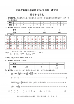
2025届浙江省新阵地联盟高三10月联考数学答案
分类:中学教育
时间:2025-12-31
标签:无
格式:PDF
价格:10 玖币
-
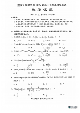
2025届重庆市西南大学附属中学高三下学期5月全镇模拟数学试题(含答案)
分类:中学教育
时间:2025-12-31
标签:无
格式:PDF
价格:10 玖币
-

2025届重庆康德三诊英语+答案
分类:中学教育
时间:2026-01-03
标签:无
格式:PDF
价格:10 玖币